What is mechanism?
When one of the links of kinematic chain is fix when chain is known as mechanism.
(If the mechanism having four links is known as simple mechanism. & If more than four links is known as compounding mechanism.)
Single slider chain mechanism types :-
1) Pendulum pump.
2) Oscillating cylinder.
3) Rotary IC engine / Genome mechanism.
4) crank & slotted lever quick return motion mechanism.
5) With worth quick return motion mechanism.
1) Pendulum pump :-
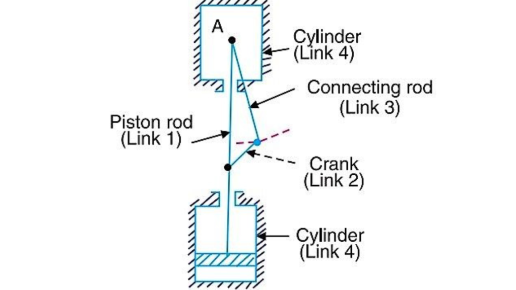
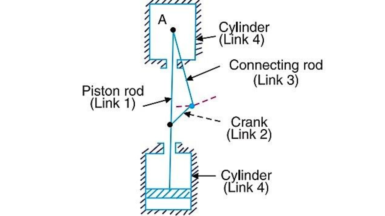
1) As shown in fig this mechanism two fixed cylinders having & for four links.
2) From fig the piston rod is link one it is attach to be crank is link 2. Which attached to be connecting rod links 3. Which is attached to be fixed cylinder that is link 4
3) When crank rotate the connecting rod will be oscillate with respect to fixed cylinder that time the piston rod reciprocate with piston. inside this cylinder.
4) The purpose of this mechanism is to convert rotary motion into reciprocated motion.
For eg. It is used in bore well to such this water.
2) Oscillating cylinder :-
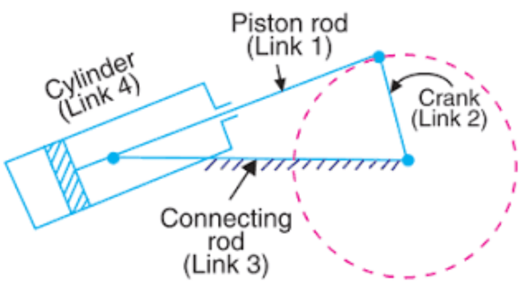
1) As shown in fig oscillating cylinder mechanism having a fixed link that is connecting rod & other are turning link or Pair.
2) When piston rod that is link (1) reciprocated inside the cylinder that piston that time the cylinder that is link (4) oscillate with respect to Point A.
3) Because of the reciprocating & oscillating motion of the link (1) & (4). The crank will be rotated with fixed point o.
4) The purpose of this mechanism is to convert reciprocating motion into rotary motion.
3) Rotary IC engine / Genome mechanism :-
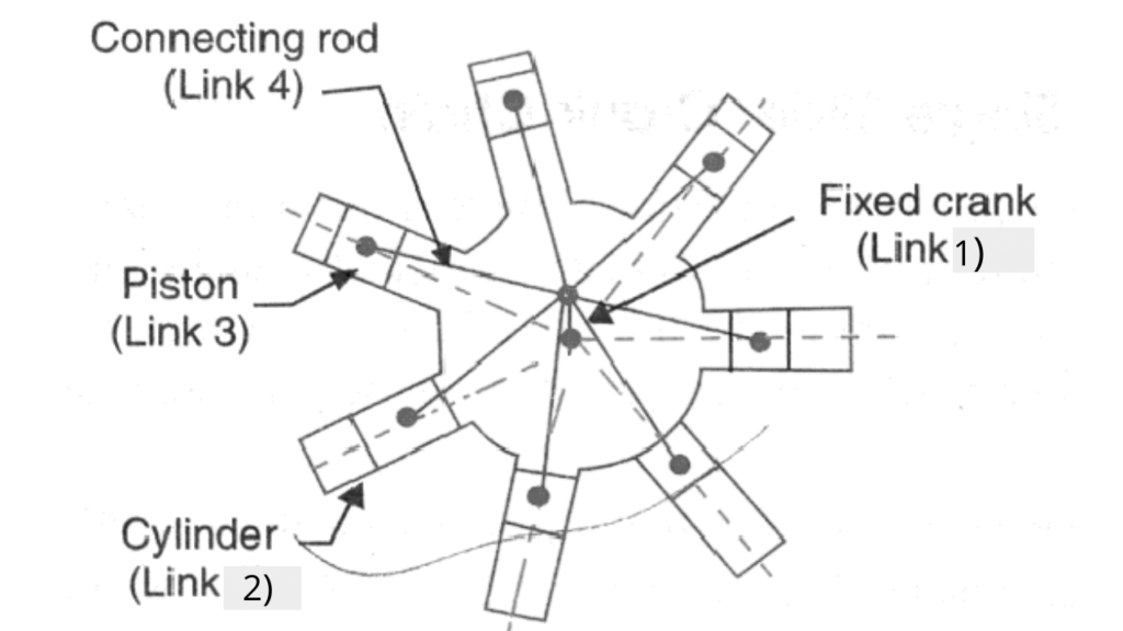
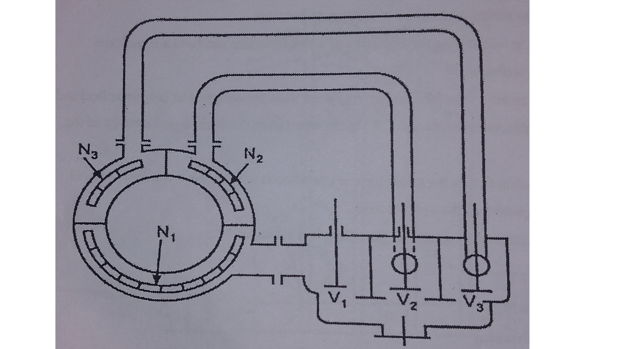
1) The rotary engine mechanism is consist of 7 cylinder in one plane & it revolve with fixed center (B). Where crank is fixed.
2) When cylinder rotate with respect to fixed center (A). The piston will be reciprocated Inside the cylinder where power will be generated the because of the reciprocating motion of piston.
3) The purpose of this mechanism the convert rotary motion into reciprocating motion.
4) For eg. The rotary motion is used in aviation, (Planes) where large amount of power supply is required. Now, A days the rotary IC engine is replaced by gas engine ( gas turbine).
4) Crank & lever slotted lever quick return motion mechanism :-
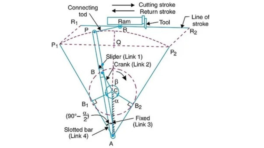
1) Crank and slotted lever is used shaping & slotted machine, as shown in fig. There are four links. The link (3) that is AC is fixed link.
2) The crank CB rotates in clock wise direction with uniform angular speed.
3) The end point of crank ‘B’ is nothing but a slider which slides inside the slotted bar “Ap” and a slotted bar is oscillate with respect to fixed point ‘A’.
4) The end point of slatted bar ‘P’ connected to Point R (Ram) by a small link. That is connecting rod. The Ram is hold by cutting tool.
5) When a crank CB1 rotates in clockwise direction with uniform angular speed to CB2, in angular bita that time the slotted bar oscillate form AP1 to AP2 Similarly the Ram will be reciprocated form point R1 R2 which is me nothing but is cutting strock.
6) Similarly, a return strock the crank CB2 rotate in anticlockwise direction with uniform angular speed to CB1 in angular alpha that time the slotted bar will oscillate form AP2 to AP1, at ram will be reciprocate from R₂ to R1.
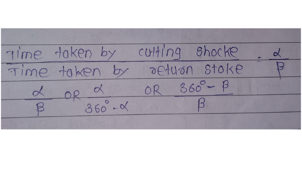
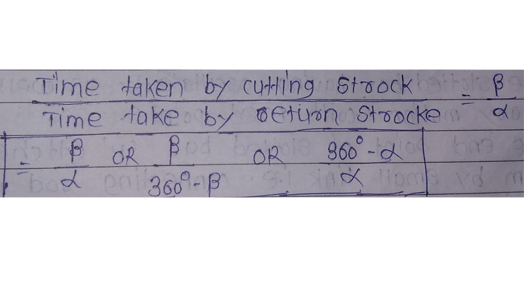
7) The time taken by the cutting strock is always equal to time taken by the crank rotates from CB1 to CB₂ ie. angle Bita.
8) Similarly the time take by return strock in always equal to time taken by crank rotates form CB₂ to CB1. ie. angle alpha.
9) The uniform angular speed of Crank is given by,
5) With worth quick return motion mechanism :-
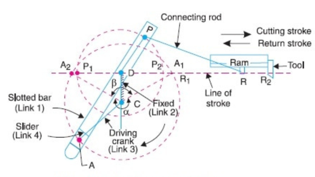
1) The with worth quick return motion mechanism is used in shaping and slotting machine’s as shown in fig link ‘CD’ in fixed link.
2) The driven crank ‘CA ‘ rotates in clockwise direction with uniform angular speed. The end point of crank ‘A’ is a slider which slide’s inside the slotted bar.
3) The slotted bar having oscillating as well as rotary motion with fixed point D.
4) The end point of slotted bar ‘p’ attched to the ram by small link ie. connecting rod which reciprocate in path R1 & R2.
5) When the driven crank CA rotates anticlockwise direction with uniform angular speed
from CA1 to CA2 of angle alpha & Point ‘P’ will be moves process P1 to P2 then the ram will be reciprocate from R1 to R2 which is the cutting strock.
6) In return strock when the Crank rotates form CA2 to CA1 at angle bita the point ‘B’ is moves form P₂ to P1 and the ram will be reciprocate from R₂ to R1 .
7) The time taken by cutting strock is always equal to time taken by crank rotates form CA2 CA1 that is angle alpha & and time taken by return strock is equal to time taken by crank rotates from CA 2 to CA1 that is angle bita.
8) The uniform angular speed by Crank is given by,
